Introduction:
Mechanical ventilation doesn’t have to be intimidating. If you are a non-ICU doc who just wants to feel more prepared when your patient gets intubated, this post is for you! I’m pretty sure after this, you won’t shy away from the ventilator again.
So grab a coffee, and let’s finally make sense of mechanical ventilation. Let’s get started.
Concept (1): The respiratory cycle has two phases: expiration and inspiration.
Inspiration is an active process that requires energy. Expiration is typically passive, relying on the lungs’ natural elastic recoil.
The respiratory cycle duration is calculated by dividing 60 seconds by the respiratory rate (RR). This cycle encompasses both inspiratory and expiratory time. The relationship between inspiration and expiration is not equal; physiologically, the ratio of inspiratory time to expiratory time (I:E) is typically 1:2 or 1:3, with expiration being longer than inspiration.
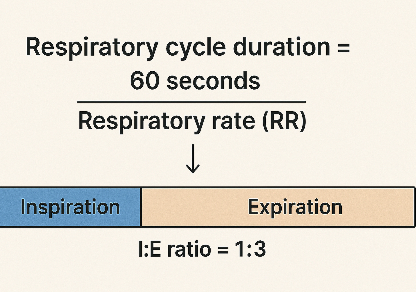
Example:
RR = 20 breaths/minute
The respiratory cycle duration = 60/20 = 3 seconds
Using I:E ratio of 1:3, the inspiratory time would be 0.75 seconds, and the expiratory time would be 2.25 seconds.
Concept (2): The ventilator does the heavy lifting during inspiration, but it doesn’t clock out during expiration!
As we mentioned earlier, inspiration is an active process that requires energy, so the ventilator works mainly during this active, energy-consuming phase. But that doesn’t mean the ventilator just shuts off during expiration—it continues to play a crucial role by maintaining a certain level of pressure that is called PEEP, or Positive End-Expiratory Pressure.
PEEP prevents the alveoli from collapsing at the end of expiration by holding a small amount of pressure in the lungs throughout the entire respiratory cycle, not just during the expiration phase. Think of it like a doorstop that keeps the alveoli slightly open, making the next breath easier and improving oxygenation.

Don’t be fooled by the name—PEEP isn’t just at the end of expiration. It’s present throughout the entire respiratory cycle. During expiration, it’s the only pressure applied, and during inspiration, the ventilator adds pressure on top of the PEEP to deliver the breath.
Concept (3): Air flows from higher-pressure to lower-pressure areas.
During inhalation, air enters the lungs because the pressure at the nose and mouth is higher than in the alveoli. During exhalation, the pressure in the alveoli becomes higher than at the airway opening, so air flows out. This air movement continues as long as a pressure gradient exists. In spontaneous breathing, we actively lower the pressure inside the alveoli below atmospheric pressure, creating suction and pulling air in.
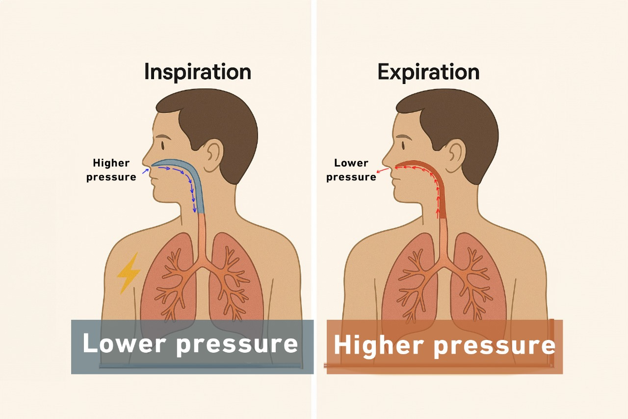
In mechanical ventilation, the ventilator does the opposite: it raises the pressure at the nose and mouth above alveolar pressure to push air in. That’s why we call it a positive pressure breath
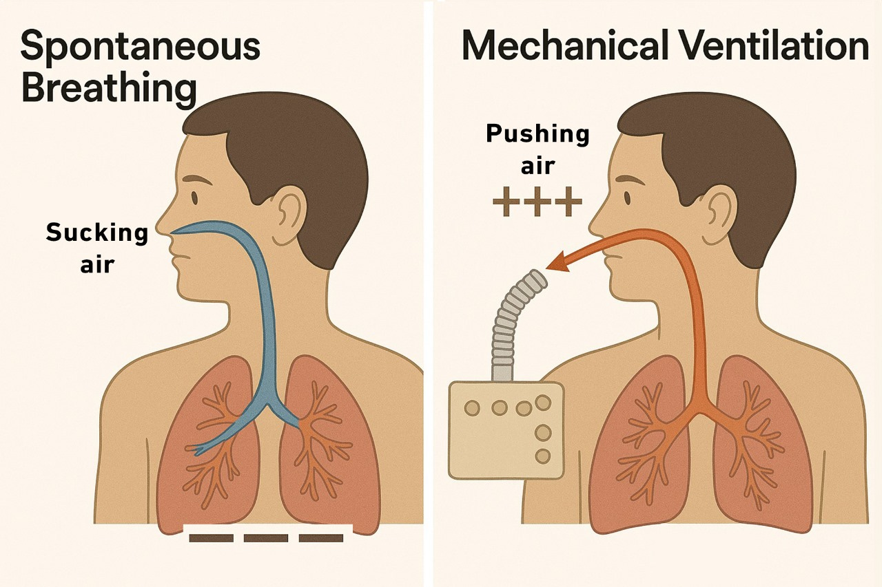
In spontaneous breath, we suck the air in; while in positive pressure breath, the ventilator pushes the air in.
Concept (4): To get air in, the ventilator has to fight three battles: the tube, the airways, and the lungs.
During mechanical ventilation, the ventilator delivers air through the endotracheal tube (ETT), down the airways, and into the alveoli. To do this, it must overcome two main types of resistance:
- The airway resistance (from the ETT and conducting airways).
- The elastic resistance (from the alveoli and lung tissue).
The airway resistance
This resistance is primarily due to their narrow lumens and flow dynamics. The pressure required to overcome this kind of resistance is called Resistive pressure, and it is calculated by multiplying the flow by the airway resistance.
Resistive Pressure = Flow (F) × Resistance (R)
The elastic resistance
The alveoli are evaluated based on their compliance—their ability to stretch and accommodate volume. The pressure required to overcome alveolar and lung tissue stiffness is called Elastic pressure, and it’s calculated by dividing volume by compliance.
Elastic pressure = Tidal volume (TV) ÷ Compliance (C)
In mechanical ventilation, the volume here simply represents TV, and the elastic pressure represents the alveolar pressure, so the equation can be rewritten as:
Alveolar pressure = TV/C
Therefore, for a full breath to be delivered, the ventilator must generate enough total pressure to overcome both the resistive and elastic or alveolar pressures. In mechanical ventilation, this pressure is called the peak inspiratory pressure (PIP).
Peak inspiratory pressure (PIP) = Resistive pressure + Elastic pressure.
Which can be rewritten as:
PIP = (F x Airway resistance) + (TV/C)
Based on this equation:
- PIP is proportionally related to Flow, airway resistance, and TV.
- Inversely related to compliance.

Take a peek at this ventilator screen: The PIP is 20 cmH2O, the flow rate is 44 L/min, and the tidal volume is 500 mL.

- Guess what will happen to the PIP if I increase the flow or the tidal volume? Based on the equation, the peak inspiratory pressure (PIP) will increase.
- What will happen to the PIP if the patient bites the endotracheal tube or develops bronchospasm, both of which increase airway resistance? Again, you’ll also see a rise in PIP.
- Let’s say the patient develops pulmonary edema and bilateral pleural effusion. What would happen to the PIP in such a case? Pulmonary edema and bilateral pleural effusion reduce the alveoli’s ability to accommodate tidal volume (reduce their stretchability and compliance). PIP is inversely related to compliance; now the ventilator has to push harder to get the breath in, which means higher PIP is required!
Concept (5): Plateau Pressure: Your Window into Lung Compliance
Let’s imagine a moment when the flow drops to zero— this occurs briefly at the end of inspiration, just before expiration begins, and again at the end of expiration, just before the next inspiration starts. These are the transition points between phases of the respiratory cycle when there’s no airflow because the pressures between the airway and alveoli are equal.
Guess what happens to the PIP when the flow drops to zero? Let’s go back to our equation:
PIP = (Flow×Resistance) + (Tidal Volume/Compliance)
If the flow drops to zero, the resistive component disappears, and the equation simplifies to:
PIP = TV/Compliance = Alveolar Pressure.
This means when the flow is zero, the PIP is equal to the alveolar pressure, and this makes sense as pressure gradient means flow, and the absence of the gradient means no flow.
In mechanical ventilation, the pressure measured at the end of inspiration when the flow ceases is known as the Plateau pressure. Plateau pressure provides great insight into lung compliance. The lower the plateau pressure, the more compliant, stretchable, and less stiff the lung is, and vice versa!

How do we measure the plateau pressure? Plateau pressure is measured using the inspiratory pause or hold maneuver. In clinical practice, we aim for a PIP < 35 cmH2O and a plateau pressure of < 30 cmH2O.
How about the opposite? I mean the pressure measured at the end of expiration and before the inspiration valve opens? What do you think the alveolar pressure should be in such a case? We mentioned earlier that PEEP is the only pressure the ventilator provides during expiration, which means the expiratory flow will continue until the alveolar pressure drops from the maximum value at the end of inspiration (plateau pressure) down to the PEEP value, when the flow ceases. So normally, the alveolar pressure measured at the end of expiration when there is no flow must equal PEEP.
To confirm that, we perform what we call the expiratory pause maneuver. This maneuver allows us to check for any gas trapping and autoPEEP.
Concept (6): The ventilator can’t think for itself—it needs our guidance
For the ventilator to function properly, we have to give it five instructions:
- When to start the breath.
- How to deliver the breath.
- When to terminate the breath.
- How much oxygen to give?
- How much PEEP to give?
1. When to start the breath or inspiration?
The ventilator listens to the patient to detect the patient’s inspiratory effort. It will pick up any inspiratory effort as a sign that the patient is trying to breathe, and it will assist the patient with that breath! This is known as a patient’s triggered breath or, as we call it in mechanical ventilation, an Assist breath or “A” breath.
But what happens if the ventilator doesn’t detect any patient trigger? Let’s say the patient is paralyzed or brain-dead.
In this case, the ventilator has a built-in safety mechanism: it will deliver a breath if no patient’s trigger is detected for a specific time! This is called a backup breath or, as we call it in mechanical ventilation, a Control breath or “C” breath.
Take a look at these two ventilator screens. The breath on picture A is a controlled or backup breath labeled as C breath, and the breath on picture B is an assist breath triggered by the patient and assisted by the ventilator.

But what decides how long the ventilator should wait before delivering a backup breath? This timing is based on the set respiratory rate (RR), which is known as the backup rate. The backup rate is the minimum number of breaths/minute the patient receives, even if they make no effort to breathe. The ventilator will listen to the patient for a period equal to [60 sec/backup RR] before delivering the backup breath.
Example: If the backup rate is set to 15 breaths per minute, the ventilator waits up to 4 seconds (60 ÷ 15), and if no patient’s trigger is detected, a backup breath will be delivered!
The actual RR is either equal to or higher than the backup rate, but never lower! This is important when trying to adjust the backup RR. Let’s say the backup rate is 14 and the patient is breathing at 20 breaths/min; there is no point here if you increase the backup rate to 16 because the actual RR is already higher!
Take a look at this ventilator screen, see the set backup rate at 18 while the actual RR on the top is 28. Increasing the backup rate will not have any impact unless it becomes higher than the actual RR.
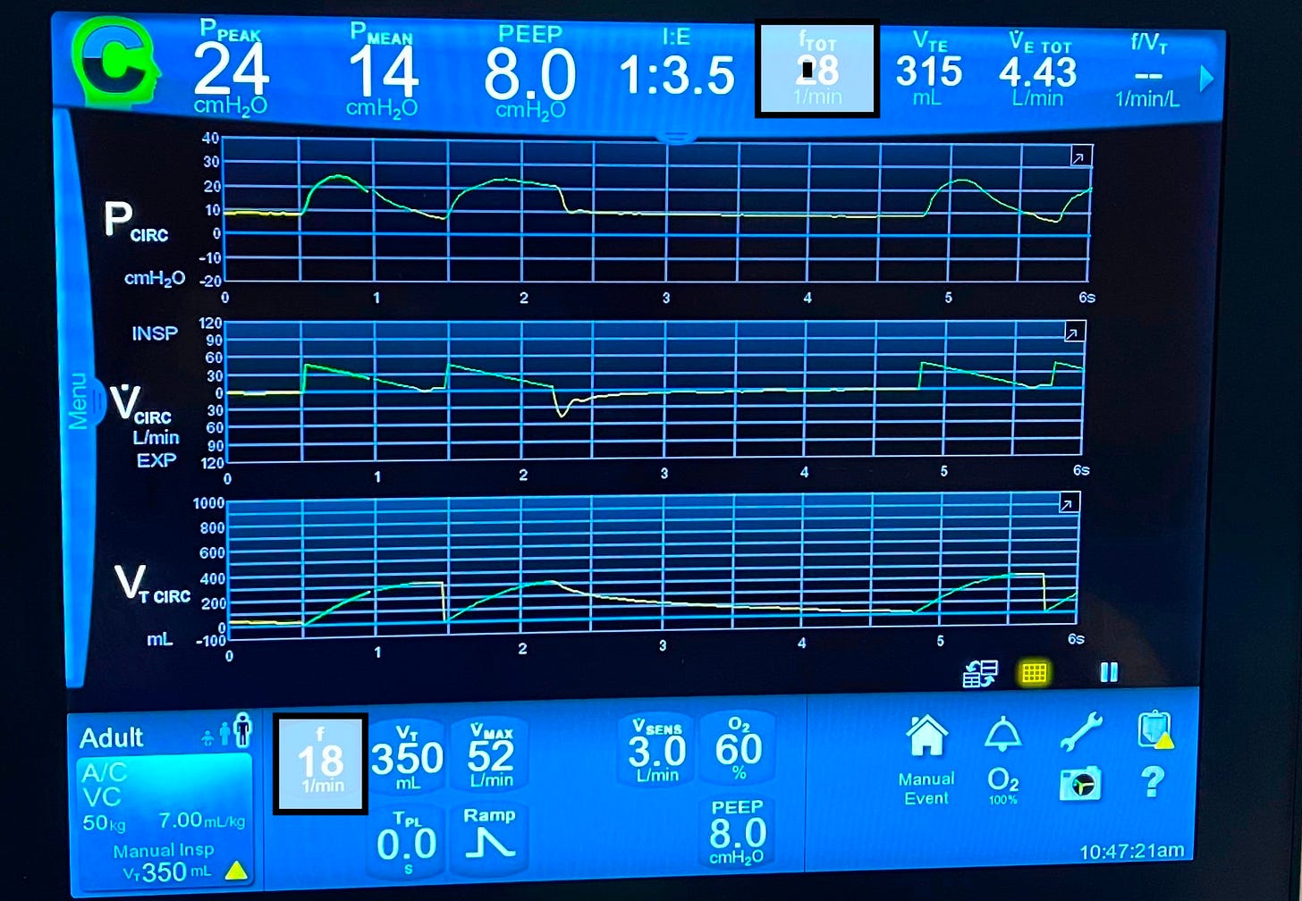
The values at the bottom of the picture are the set values that we provide, while those at the top are the actual live values! The ventilator tries to fulfill the set values or close to them (See the set TV is 500, but the actual one is 524).

Back to the trigger, how does the ventilator detect the patient’s trigger?
In spontaneous breathing, the patient generates negative pressure in the alveoli, which creates a suction effect that pulls air in. When the patient is intubated and connected to a ventilator, this same effort draws air through the circuit, and that’s how the ventilator knows it’s time to assist.
Take a look at the ventilator circuit picture below: you’ll notice two limbs connected to the endotracheal tube (ETT)—the inspiratory limb, which carries air from the ventilator to the patient (often passing through a humidifier), and the expiratory limb, which returns air from the patient back to the machine.
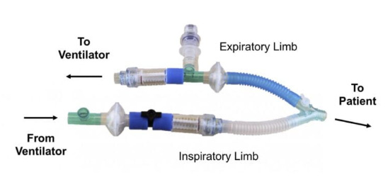
When the patient is not making any effort, air flows equally through both limbs. When the patient initiates a breath, he pulls some air from the inspiratory limb into his lungs, reducing the flow returning through the expiratory limb. The ventilator senses this imbalance and interprets it as an inspiratory effort and will go ahead and assist the patient with that breath. This is called a flow trigger.
Alternatively, the ventilator can detect a drop in airway pressure (caused by the patient’s inspiratory effort) and use that as a trigger. This is called a pressure trigger.
🔁 To summarize: the ventilator can recognize a patient’s attempt to breathe in two ways:
- Flow Triggering – by sensing a drop in flow through the expiratory limb.
- Pressure Triggering – by sensing a drop in airway pressure.
Take a look at these two screenshots of two ventilators:

- On Picture A, Psens shows the pressure trigger. It’s set at 2 cm H₂O, meaning the patient must reduce his airway pressure by at least 2 cm H₂O to trigger a breath. We usually set this between 2 and 3 cm H₂O.
- On picture B, Vsens represents the flow trigger, set at 3 L/min. This means the patient must draw in at least 3 L/min (approximately 50 mL/sec) for the ventilator to deliver a breath.
Whether using a flow trigger or a pressure trigger makes no clinical difference—neither offers a clear advantage over the other.
2. How should the ventilator deliver this breath?
In mechanical ventilation, we refer to the way of delivering the breath as the “target.” Although the term can be confusing, the concept is straightforward—just give me your full attention!
Let’s bring back our lovely equation again:
PIP = (F x R) + (TV/C).
Which can be rewritten as: PIP = (F x R) + Alveolar pressure. Which can be rearranged into: F = (PIP – Alveolar pressure) / Resistance.
In mechanical ventilation, we can directly set the flow rate and the peak inspiratory pressure (PIP) on the ventilator. However, alveolar pressure and airway resistance are not directly settable—they’re influenced by the patient’s lung mechanics and underlying condition.
Based on the equation, mathematically, for the pressure–flow relationship to hold true, we can only set one variable—either the pressure or the flow, but not both. That’s because one must remain flexible to allow the other to stay fixed. If we fix both, the equation wouldn’t hold under changing patient conditions.
This will leave us with one of two options to deliver the breath:
- You can either set the flow and let the pressure adjust, which is called the flow target.
- Set the pressure and let the flow adjust, which is called the pressure target.
In flow-targeted ventilation, we start by setting the desired flow rate. From there, we have two main subtypes based on how that flow is delivered:
- We can ask the ventilator to keep the flow rate fixed throughout the inspiratory phase, which results in a square or rectangular flow vs time curve.
- Or we can ask the ventilator to give the set flow rate only at the beginning of the breath, and let it progressively drop or decelerate throughout the rest of the inspiratory phase! This results in a decelerating ramp flow vs time curve.
In clinical practice, we primarily use the decelerating ramp flow, it generally results in a lower peak inspiratory pressure (PIP) compared to the constant (square) flow pattern.
Take a look at this flow target on this ventilator screen and notice:
- The green curve shows the decelerating ramp flow pattern.
- On the info panel, the flow target is set at Vmax: 44 L/min with the ramp type set to decelerating.

How about the pressure target ventilation?
Here, we tell the ventilator to apply a fixed amount of pressure on top of the PEEP throughout the inspiratory phase until the breath is delivered.
What do you think the flow pattern will be in the pressure target? To maintain a fixed pressure throughout the inspiratory phase, the flow must progressively decrease to keep this equation valid, “F = (PIP – Alveolar pressure) / Resistance”. Of course, as long as the resistance is constant. That’s why the flow vs time curve is always a decelerating ramp curve in pressure target modes.
Take a look at this ventilator screen, see the fixed pressure here. The ventilator adds 20 cmH2O on top of PEEP of 10 and keeps it there during the whole inspiration. The flow curve is a decelerating ramp curve.
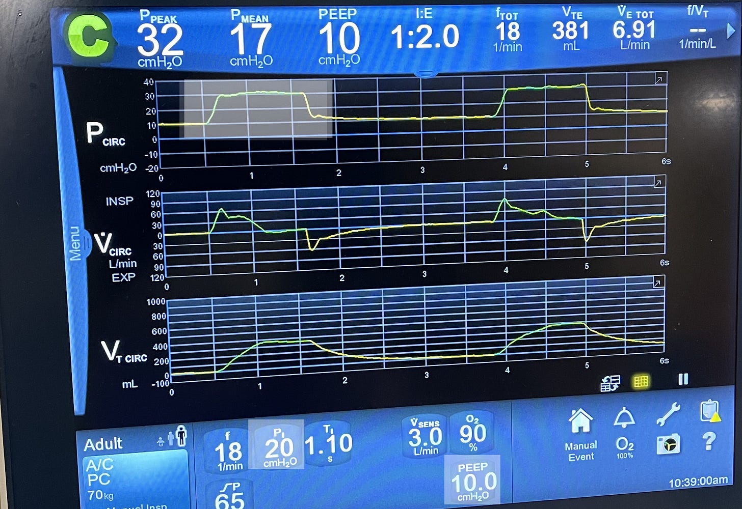
What do you think will happen to the flow rate if we set the inspiratory pressure (Pi) at 30 cmH2O instead of 20?
If we increase the inspiratory pressure from 20 to 30 cmH₂O, the flow rate will increase; so the higher the set pressure, the greater the initial flow the ventilator delivers.
3. When should the ventilator stop delivering the breath (Cycle)?
This is known as the ‘cycle’ in mechanical ventilation. There are three main mechanisms to determine when the ventilator stops inspiration and switches to expiration. These are known as cycling mechanisms:
Volume-Cycled Ventilation:
In volume-cycled breaths, the ventilator ends inspiration once the preset tidal volume (TV) is delivered.
🔍 Look at the ventilator screen below and see the volume vs time curve. Once it reaches the desired TV, it will switch from green color, which represents inspiration, to yellow color, which represents expiration. Also, look at the top panel and see that the actual TV was 315! In reality, the ventilator doesn’t always fulfill the exact set TV, but it will be close to that!
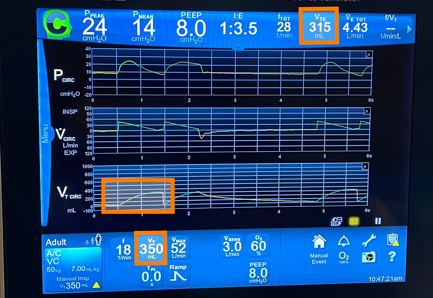
What do you think will happen to the inspiratory time if we increase the TV here? Of course, it will increase; the larger the volume, the longer it takes to deliver it. The opposite is true.
Time-Cycled Ventilation:
In time-cycled breaths, the ventilator switches to expiration after a preset inspiratory time has elapsed, regardless of the volume delivered.
🔍 Check the ventilator screen for the set inspiratory time and see that the green line in all the curves switches to yellow after the set inspiratory time.
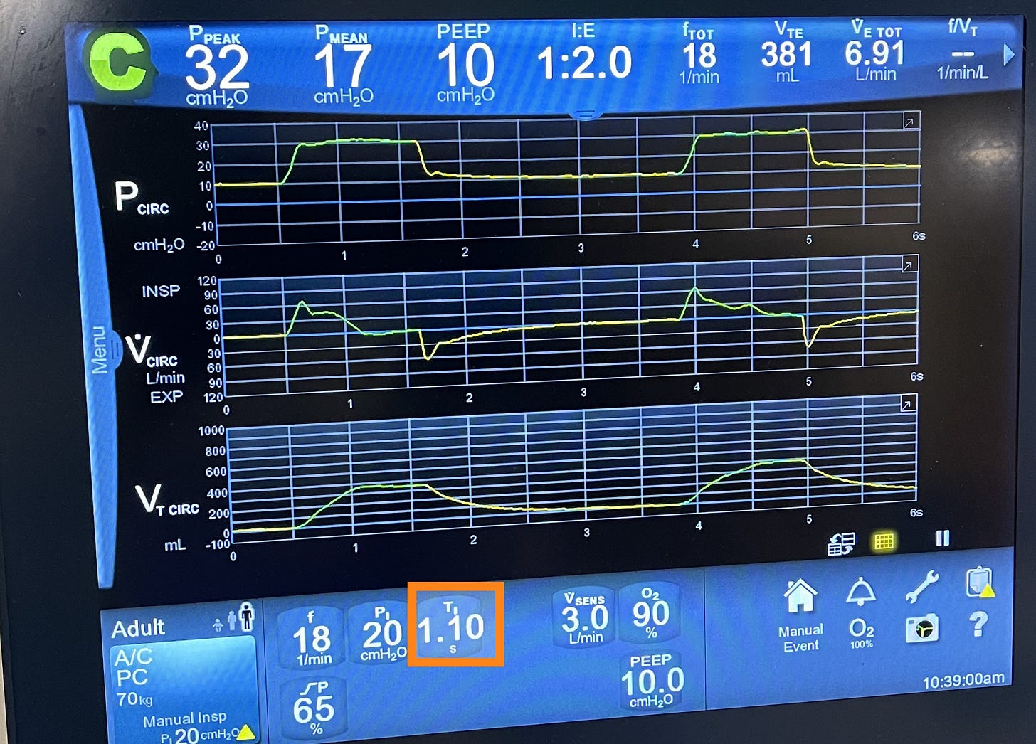
What do you think the TV will be if we shorten the insp time? It will be smaller as we spending less time delivering the breath, the opposit is true.
Flow-Cycled Ventilation:
In flow-cycled breaths—used primarily in pressure support mode—the ventilator ends inspiration when inspiratory flow drops to a preset percentage of peak inspiratory flow.
🔍 Look at this screen and see the “Esens” or expiratory sensitivity setting (commonly set at 25%)—the breath ends when flow falls to 25% of its peak during inspiration.
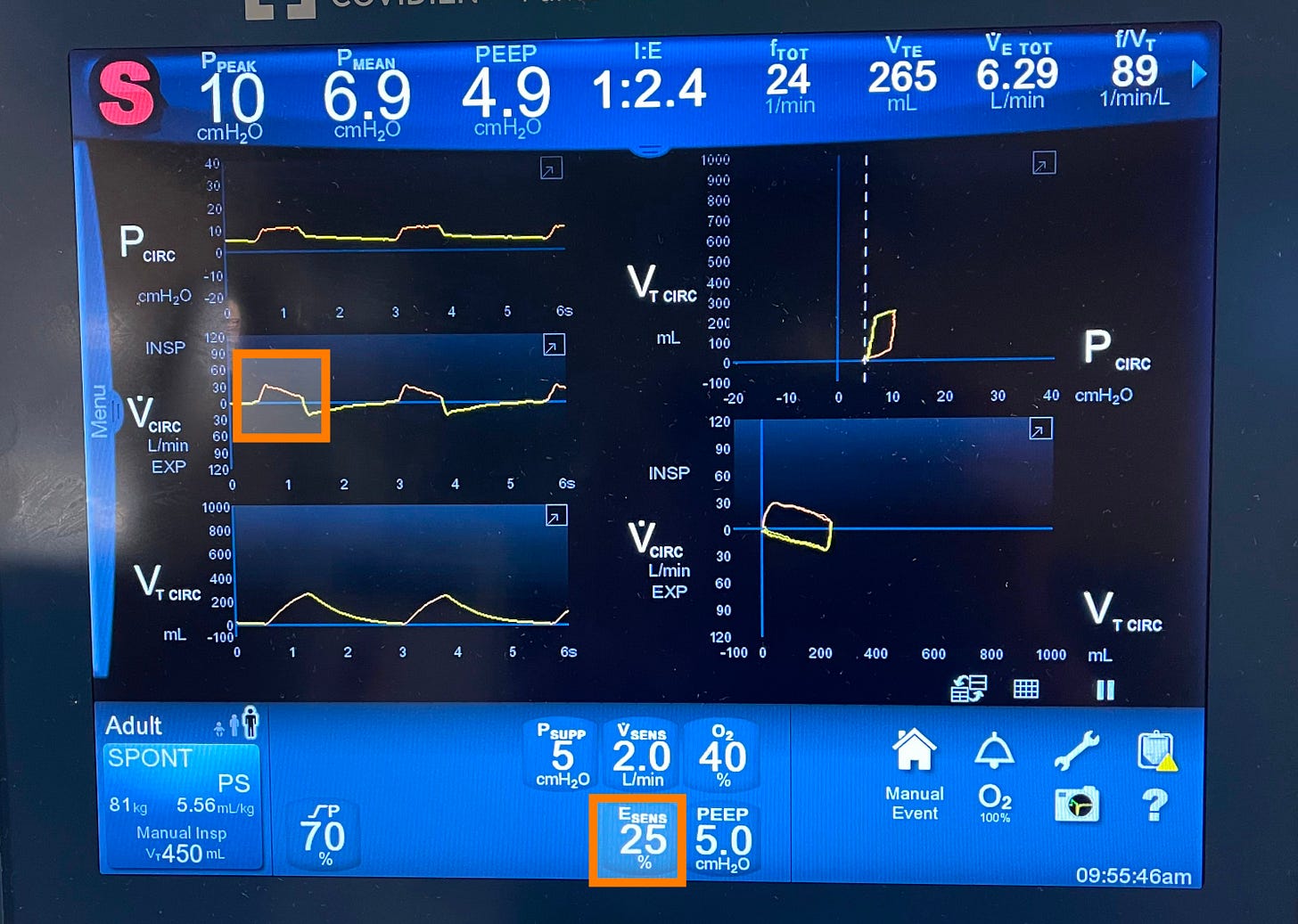
What will happen to the TV if we set ESens at 50% instead of 25%? It will be smaller as we are having a shorter inspiratory time! The opposite is true.
4. How much FiO₂ and how much PEEP? These two are oxygenation parameters, and we’ll discuss them later in this post.
Concept (7): Every Mode Is a Recipe: You Just Change the Ingredients
At the heart of mechanical ventilation are three fundamental modes:
🔹 Volume Control.
🔹 Pressure Control.
🔹 Pressure Support.
Every other mode you’ll encounter is either a hybrid or a modification of these three.
To make sense of any mode, just break it down into the three key ingredients we just explained:
🟢 Trigger – What starts the breath?
🟡 Target – How to deliver the breath?
🔴 Cycle – What ends the breath?
Before I go further!
If you’re finding this helpful, you’re going to love my full mechanical ventilation course. It covers everything we’re walking through in this video—from triggers, targets, and cycling to all the core modes—plus much more, like: Troubleshooting PIP, Rise time, Mean airway pressure, Auto-PEEP and gas trapping, Assessing weaning readiness, and how to do a proper weaning trial.
It’s designed to walk you through mechanical ventilation step-by-step, in a way that’s clear, visual, and practical.
If you’re ready to truly master the vent and feel confident at the bedside, check out the course.
Volume control or VC mode
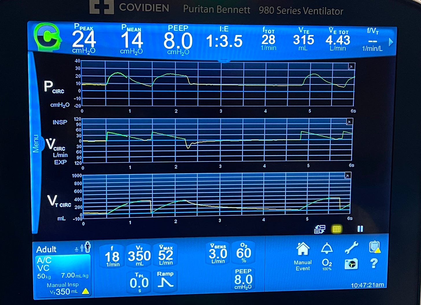
- Trigger: VC mode typically uses assist/control (A/C) triggering. As we explained earlier, the ventilator delivers a breath either when the patient initiates one or, if the patient doesn’t, the ventilator will trigger a breath based on the set backup respiratory rate.
- Target: VC mode is flow-targeted, commonly using a decelerating ramp flow pattern.
- Cycle: VC is volume-cycled, meaning the breath ends once the preset tidal volume (TV) has been delivered.
So when ordering VC mode, in addition to the FiO2 and PEEP values, we need to provide the respiratory therapist with the following values:
- The backup RR.
- The TV.
- The Flow curve: square or decelerating.
- The Peak flow rate.
In most cases, RT will, by default, pick a decelerating ramp flow curve and set the peak flow rate; a reasonable starting peak flow rate is between 40-60 L/min.
Take a look at this VC mode screenshot,
Pressure Control (PC) Mode
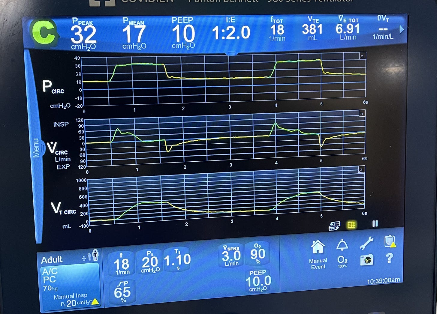
- Trigger: Like VC mode, PC mode uses assist/control (A/C) triggering, meaning the breath can be triggered either by the patient’s effort or by the ventilator’s set backup respiratory rate if no spontaneous inspiratory effort is detected.
- Target: As the name suggests, PC mode is pressure-targeted. The ventilator delivers a breath by applying a set inspiratory pressure above the PEEP, and adjusts flow as needed to maintain that pressure throughout inspiration.
- Cycle: PC mode is time-cycled—the breath ends when the set inspiratory time has elapsed, regardless of how much volume was delivered.
When ordering PC mode, in addition to the FiO2 and PEEP values, we need to provide the respiratory therapist with the following values:
- Back up RR.
- Pi or inspiratory pressure, this is the pressure that will be added on top of the PEEP during inspiration.
- Ti or inspiratory time, this is the time the inspiratory pressure will be applied for.
Pressure support (PS) mode
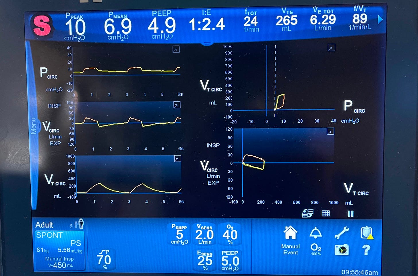
- Trigger: This mode is patient-triggered only—there’s no backup respiratory rate. That’s why it’s suitable only for awake, spontaneously breathing patients, typically during the weaning phase of mechanical ventilation.
- Target: PS mode is pressure-targeted, similar to PC mode. The ventilator delivers a breath by applying a set inspiratory pressure above PEEP to assist the patient’s spontaneous effort.
- Cycle: PS mode is flow-cycled. The breath ends when the inspiratory flow decreases to a preset threshold, usually 25% of the peak inspiratory flow.
When ordering PS mode, in addition to FiO2 and PEEP values, we provide the respiratory therapist with the following values:
- Inspiratory pressure. In this mode, it’s called Pressure support.
- The flow cycle percentage is typically 25%.
There’s no backup RR because it only uses the patient’s trigger.

Concept (8): No Mode is perfect!
Each mode has its advantages and limitations.
Key Differences in Volume, Pressure, and Support Modes:
- Volume Control (VC):
You’re guaranteed a set tidal volume, but there’s no cap on peak inspiratory pressure (PIP)—it can rise significantly if the lungs are stiff or airways are tight. - Pressure Control (PC):
The PIP is controlled and capped at the set level, but the tidal volume will vary based on the patient’s lung compliance and airway resistance. - Pressure Support (PS):
Similar to PC, PIP is limited by the set pressure support level, but tidal volume is not fixed. This mode is patient-triggered and commonly used for weaning.
How about if I take the good stuff from each mode? If I take the set tidal volume from VC mode and the controlled inspiratory pressure from PC mode? Well—that’s exactly how PRVC (Pressure-Regulated Volume Control) was born!
In PRVC, you set the tidal volume you want delivered along with the maximum pressure limit—this acts as a safety cap, not the actual pressure used in each breath.
Here’s how it works:
The ventilator adjusts the inspiratory pressure breath-to-breath to deliver the set tidal volume, while keeping the pressure as low as possible.
If the patient’s lung compliance worsens (like in ARDS), the ventilator will increase the pressure trying to maintain the tidal volume—but only up to the set pressure limit.
If compliance improves, the ventilator will lower the pressure accordingly.
If the pressure needed to deliver the tidal volume exceeds the set limit, the ventilator won’t go higher—it will under-deliver the volume and often trigger a low tidal volume alarm. That’s why choosing a reasonable pressure limit is important, especially in patients with stiff lungs.
Some ventilators also require or allow you to set an inspiratory time (Ti) in PRVC mode. If used, Ti helps shape how long the inspiratory pressure is applied. A longer Ti can help improve alveolar recruitment and oxygenation in patients with stiff lungs, while a shorter Ti may be needed in patients with obstructive lung disease to prevent air trapping.
So, in addition to FiO₂ and PEEP, the following parameters are typically set in PRVC:
- Backup respiratory rate, since it uses an A/C trigger.
- Tidal volume, because it’s volume-cycled.
- Maximum pressure limit, as a safety guard to prevent barotrauma.
- Inspiratory time (Ti), on some vents, to control the duration of pressure delivery and fine-tune I:E ratio.
Take a look at this ventilator screen (notice this particular ventilator manufacturer calls PRVC mode VC+)
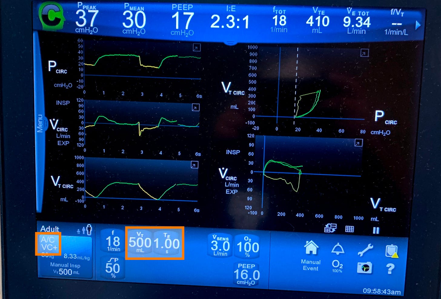
SIMV (Synchronized Intermittent Mandatory Ventilation) is essentially a blend of VC or PC with pressure support. I won’t dive deeper into SIMV here, as I rarely use it in practice today, and there’s no strong clinical justification for choosing it over other modes.
Current evidence does not support the superiority of SIMV, VC, PC, or PRVC over one another in terms of clinical outcomes for patients with acute respiratory failure or other critical care conditions.
The choice of ventilation mode should always be individualized, based on the patient’s clinical status, lung mechanics, and response to therapy! I like PRVC as it may offer advantages in terms of lower peak inspiratory pressures and more stable gas exchange, making it a reasonable first choice among the three modes.
Concept (9): Tuning the Vent (Oxygenation vs. Ventilation)
When managing a ventilated patient, it’s crucial to understand what you’re trying to fix—are you trying to improve oxygenation or ventilation?
These are two distinct goals, and each is managed by adjusting different ventilator settings:
- To improve oxygenation, we focus on increasing FiO₂ and PEEP.
- To improve ventilation ( CO2 removal), we adjust the tidal volume (TV) and respiratory rate (RR).
Knowing which “knob to turn” allows you to make targeted, effective changes based on your patient’s needs—without overcomplicating things.
Hypoxia
I typically start with an FiO₂ of 100% and a PEEP of 10 cmH₂O. From there, I aim to wean the FiO₂ as quickly as possible, targeting ≤60% to minimize the risk of oxygen toxicity.
I avoid reducing PEEP until FiO₂ is down to 60% or less. If I can’t lower FiO₂ safely, I’ll consider increasing PEEP—usually in increments of 2–4 cmH₂O—to improve oxygenation. But keep in mind: raising PEEP will also increase peak inspiratory pressure (PIP).
For refractory hypoxemia, there are additional advanced strategies—such as recruitment maneuvers, paralytics, inhaled pulmonary vasodilators, and ECMO—which are beyond the scope of this video and should be managed by an intensivist.
And don’t forget: in patients with ARDS, early prone positioning is a key intervention that can significantly improve oxygenation.
Ventilation
When it comes to improving ventilation (i.e., CO₂ removal), the two main variables we adjust are the tidal volume (TV) and the respiratory rate (RR).
✅ Key Principles:
- Always use predicted body weight (PBW)—not actual body weight—to calculate tidal volume.
- In ARDS, we aim for a lung-protective strategy:
➤ 6 mL/kg PBW - In most other conditions, a range of 6–8 mL/kg PBW is acceptable.
- In ARDS, we aim for a lung-protective strategy:
- If more ventilation is needed, it’s generally safer to increase the RR rather than the tidal volume to reduce the risk of volutrauma, but remember that the higher the RR, the shorter the respiratory cycle, which affects the I:E ratio.
🛠 How Tidal Volume Is Set (or Adjusted) in Different Modes:
- In VC and PRVC modes, the tidal volume is set directly and can be easily adjusted.
- In PC and PS modes, tidal volume is not set—instead, it depends on:
- The pressure gradient between PIP and PEEP.
- The inspiratory time.
📈 In Pressure Control (PC) Mode:
To increase tidal volume:
- Increase the inspiratory pressure (PIP).
- Decrease the PEEP (carefully, as this may affect oxygenation).
- Or do both to widen the pressure gradient.
- Increase inspiratory time (Ti) to allow more time for lung filling.
📈 In Pressure Support (PS) Mode:
It’s the same concept, just different terminology:
- The “pressure support” setting is analogous to the “inspiratory pressure” in PC mode.
- Inspiratory time is not directly set, but can be adjusted by modifying the flow cycle threshold:
- Lowering the flow cycle percentage prolongs inspiratory time.
- Raising it shortens inspiratory time.
Let’s wrap it up here! I hope this post gave you a strong foundation in mechanical ventilation and helped make things clearer and more practical for your clinical work.
If you’re ready to take it to the next level and truly master topics like PIP, mean airway pressure, rise time, gas trapping, and auto-PEEP, inverse ratio ventilation, as well as how to assess weaning readiness and perform a proper weaning trial—then check out my full mechanical ventilation course here. It’s packed with real-world explanations, visuals, and tips I’ve gathered over years of hospitalist practice. You’ll find the link below—I’d love to have you in the course!


10 Medications You Must Master Before Your ICU Rotation
Positive troponins! MI or not?
Comprehensive Guide to Antibiotic Spectrum: Gram-Positive, Gram-Negative, and Anaerobic Coverage